Understanding Suspension Geometry
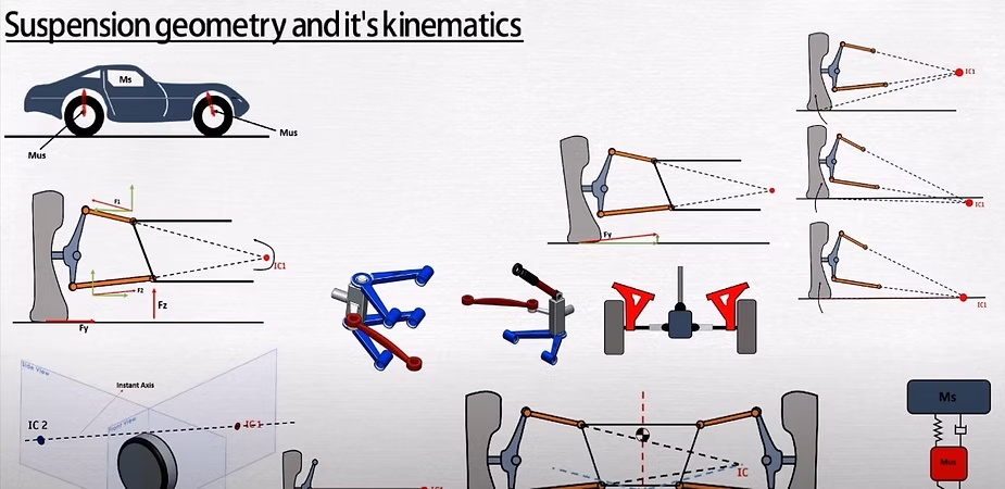
Suspension geometry refers to the broad subject of how the unsprung mass of a vehicle is connected to the spring mass. These connections not only determine the relative motion but also control the transmitted forces between them. It is important to note that each geometry must be designed specifically to meet the requirements of a particular vehicle.
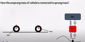
In a three-dimensional world, the motion of a single body can be defined by its three components of linear motion and three components of rotational motion. means that a single body has six degrees of freedom in motion.
For independent suspension the assembly of control arms is designed to control the motion of the wheels relative to the car body along a prescribed path. This path may include camber gain, caster change, and change as specified by the designer. However, the wheel still follows a single path it moves up and down, limiting its motion in other directions.
Tension Compression Links
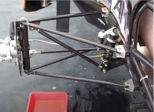
The movement of the suspension system is regulated to ensure the vehicle’s stability and control. In the front suspension, the steering system allows limited rotation of the knuckle. This restriction in motion is known as the five degrees of restraint. Essentially, the suspension limits movement in five directions. The goal is to determine how to restrain the knuckle and achieve the desired motion control.
To achieve the five degrees of restraint, a suspension system requires five tension and compression links. These links restrict the motion of the suspension components. A tension and compression link resembles a simple arm or a straight link with a ball joint at one end. Another component of suspension, the MacPherson strut, acts as a slider mechanism. It is similar to an A-arm perpendicular to the slider’s movement.
In double wishbone geometry, two A-arms are used, which effectively provide four links, and one tie rod serves as the fifth link. The MacPherson strut consists of one strut (two links), one A-arm (two links), and one tie rod (one link). Therefore, both suspension systems have five links in total, ensuring the desired motion control.
It should be noted that in suspension geometries like double wishbone and MacPherson strut, only tension and compression forces act on the links. These forces allow the links to be lightweight and thin, yet still withstand lateral forces. However, there are suspension systems with less than five links. These systems, such as the semi-trailing arm rear suspension, utilize a single arm to perform the role of five links. In such cases, the arm must be sufficiently strong to endure bending and torsion forces in three directions of rotation.
Instant Center and Instant Axis

Let’s explore the concepts of instant center and instant Axis in suspension geometry. The term “instant” implies a specific position in the linkage, while “center” refers to the pivot point of the linkage at a particular instant.
In the front view of a double wishbone geometry, extending the upper and lower arm creates a pivot point around which the linkages move at a specific instant. This pivot point is known as the instant center. As the tire moves up and down, it causes a deflection of the linkages, effectively altering the instant center. Therefore, when designing the suspension geometry, it is crucial to consider how the instant center changes with suspension travel.
To facilitate suspension design, the assembly’s three-dimensional view is often broken down into two dimensions. By projecting the linkages in the front view, we can identify the instant center. This instant center determines the role center, scrub motion, camber change, and the data necessary to study the steering characteristics.
Similarly, in the side view, projecting the linkages’ mounting points allows us to determine the instant center, which defines the wheel’s fore and aft path, entry dive, t-square geometries, and caster change. Let’s denote the instant center in the front view as IC1 and in the side view as IC2. By connecting IC1 and IC2, we obtain a line called the instant axis, which represents the motion of the knuckle relative to the car body.
Jacking and Roll Center Height
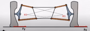
To comprehend the concept of jacking, it is essential to have a clear understanding of the roll center height. In a previous video discussing roll steer, I explained how the roll center can be determined by extending a line from the center of tire ground contact. This line intersects with another line extended from the center of ground contact for the opposite tire. The point where these two lines intersect is referred to as the roll center. The height of this point from the ground is known as the roll center height.
The position of the roll center in relation to the center of gravity and the ground has a significant impact on the handling behavior of a car. Essentially, the roll center serves as the point where the forces of the sprung and unsprung masses of the vehicle couple together.
When taking a right turn, the car experiences a centrifugal force (Fc) towards the left direction at the center of gravity. This force causes movement around the roll center. Decreasing the distance between the roll center and the center of gravity results in decreased roll movement since the movement is determined by Fc multiplied by Z2. Consequently, the degree of rolling is reduced.
However, if we decrease the distance between the center of gravity and the roll center excessively, it can lead to an undesirable effect known as jacking. By increasing the distance between the roll center and the ground, jacking occurs. Jacking is particularly evident in the front suspension geometry of a car. The left tire possesses an instant center (IC1), while the right tire has IC2.
During a right turn, each tire experiences a force (Fy) in a particular direction. This force causes the tire to roll on the left, as the movement is applied at IC1 due to the lateral force. As a result, the upper link of suspension is pushed outward by force F1 and the lower link is pushed inward by force F2. Resolving these forces into their components generates the net vertical force (Fz). This force is responsible for lifting the spring mass and is referred to as the jacking force.
Jacking force is considered unsuitable as it raises the sprung mass, effectively increasing the degree of rolling. However, in cases such as bottoming out, where the suspension reaches its maximum level of compression, jacking force helps prevent the car from bottoming out by lifting it. Therefore, while designing suspension geometry, it is crucial to position the roll center near the center of gravity and closer to the ground in order to minimize excessive jacking force.
Camber Change Rate and Scrub
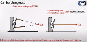
In order to comprehend the camber change rate, it is essential to familiarize yourself with the concept of the front b swing arm. In this particular geometry, the instant center (IC) holds significance.
Front View Swing Arm: The blue line extending from the contact patch to the instant center is referred to as the front view swing arm. The distance between the IC and the entire center contact patch is known as the front view swing arm (FVSA) length, while the height of the IC is called the front view swing arm (FPSA) height.
Roll Centre: The roll centre of a vehicle is determined by the FPSA height and the FPSA length. On the other hand, the camber change rate solely depends on the FPSA length.
Camber gain can be understood as the variation in the camber angle after a certain amount of suspension travel. If the control arms of the suspension are replaced by a single link connecting the knuckle to the instant center, the camber change achieved per inch of right travel can be determined using the formula: tan inverse of 1 divided by FPS in length. Consequently, a shorter FPS length results in a larger camber change rate, whereas a longer FPS length leads to a smaller camber change rate.
Another crucial factor in the front view of suspension geometry is scrub. Scrub refers to the lateral motion of the wheel relative to the ground due to vertical wheel motion. It is influenced by the length of control arms and the position of the instant center. When the instant center is positioned above the ground and inboard, the tire moves outward or “scrubs out” during jumps. Conversely, if the instant center is below the ground level and outboard, the tire moves inward or “scrubs in” during downs. The minimum scrub occurs when the instant center is located on the ground. Notably, scrub modifies the slip angle due to lateral scrubbing of the tire.
To delve deeper into suspension geometry analysis, you can refer to my videos on anti-dive caster and anti-squat geometries, which examine the side view of the suspension.